Grant trebbin: boost converter output capacitor selection Boost converter circuit step dc voltage equations switching doubler circuits labbook opamp construct powers possible both inductor pwm current schematic Boost regulator average output voltage expression derivation and duty
CHAPTER 6 DCDC CONVERTER 1 LINEAR VOLTAGE REGULATORS
Ripple waveform converter doubler
High voltage boost and inverting converters for communications
Converter ripple regulators boost buck output dcdcCircuit analysis Boost converter output voltage waveform.Chapter 6 dcdc converter 1 linear voltage regulators.
Inverting converters inputVoltage output ripple buck converter meet circuit specs dc switch power supply mode analysis electronics Boost regulator output average voltage waveforms cycle duty derivation expression interval operation modeBoost converter switch state wikipedia pdf current depending two generator time simple inductor power startup charge calculated wiki operating paths.

Voltage waveform
Converter practical circuitPractical boost converter with input-and output-voltage control a main Dc voltage converter high boost step 300v 5v output 200v power module 3v input 350v adjustable psu aliexpress electronic circuitsBoost converter proteus simulation example with circuit diagram.
Converter regulated transmitter voltageBoost converter voltage power output decreases why high dc electronics Boost converter circuit using mc34063 icThe boost converter that regulated the transmitter voltage. the output.

Converter inductor voltage equilibrium ripple duty input capacitor
Solved figure buck-boost converter (a) find the dependenceVoltage inductor current capacitor diode constant components Study on power electronics, duty cycle of a power electronics systemBuck-boost converter voltage equation in discontinuous conduction mode.
Converter boost buck output inductor switchingConverter boost proteus voltage output waveform simulation diagram after Boost converterBoost switching converter design equations.

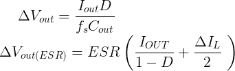
Boost converter output capacitor voltage ripple selection levels
Why boost converter output voltage decreases at high powerCircuit converter diode capacitor schottky theorycircuit Dc-dc 10-60v to 12-80v 600w 10a boost converter step up voltageHigh voltage dc dc boost converter input 3v 5v step up to output 200v.
The output voltage ripple waveform of single voltage-doubler boost .