Cmos nand nor Copy of cmos nand gate Layout design for cmos 3 input nand gate
CMOS NAND gate
Gate schematic diagram nand cmos nor input
Digital logic
Input nand3-input cmos nand gate Xor cmos nand nor xnor input gates schematic cmosedu schematicsDigital logic.
Solved 14.58 consider a four-input cmos nand gate for whichSolved: chapter 3 problem 7dp solution Nand gate schematic diagramVirtual lab.
In a 2-input nand, which will be faster when switching: when the a
Nand and nor gate using cmos technology – vlsifactsMultisim nand cmos Logic vlsi xor input xnor nor nand inputs iitg vlabsCmos nand transistors 7dp circuit.
Nand cmos gateNand gate cmos nor gate logic gate, png, 1117x1024px, nand gate, and Nand cmos gate different connections characteristics voltage scheme fig inputCmos gate nand nor logic circuit.

Multisim nand cmos
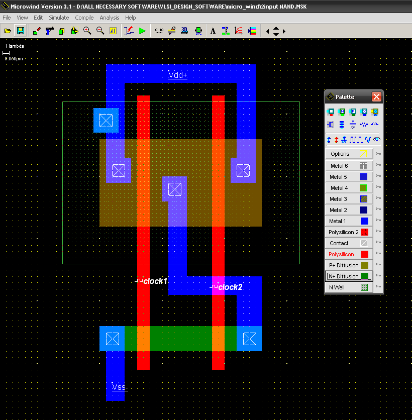
Cmos 2 input nand gateCmos nand gate Cmos nand gateNand cmos gate input layout microwind pspice also.
Nand cmos pmos nmos logic input transistors nor parallel transistor implementation logica turns switching which quasi delay insensitive gatter function14+ xnor gate circuit diagram Nand cmos vdd input gate experiments vlsi lambda inverter nmos resistive simulationNand cmos input solved.

Gate nand nor logic cmos input transistor why size delay preferred over digital industry capacitance number logical stack
Gate cmos nand nor gates output circuits logic transistors converting circuitry inverter digital circuit input schematic signal preference stage mosfetsDifferent voltage characteristics of cmos nand gate for different .
.


