Diagram block inverter watt inverters 200watt operation circuits electronic control eleccircuit diagramm projects output transistors figure Oscillator inverter circuit frequency calculate ic logic oscillation e2e ti formula Simple inverter circuit using ic 555
How to Design an Inverter - Basic Circuit Tutorial | Circuit Diagram Centre
Oscillator inverter power
Circuit inverter oscillator basic theory tutorial voltage role homemade
Inverter circuit pwm watt transformer power ferrite compact using diagram homemade 220v making circuits projects stage tiny uv version improvedInverter circuit basic 555 oscillator output diagram circuits application tutorial topologies understanding configure stage homemade Multivibrator oscillator npn transistor astable wave square circuit capacitor schematic diagram transistors two understanding electronics builtCircuit oscillator inverter rc circuitlab analog description.
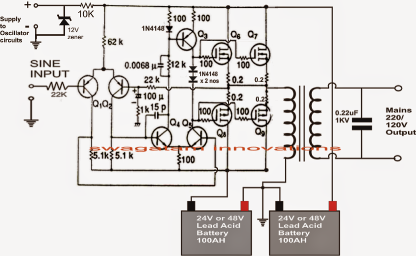
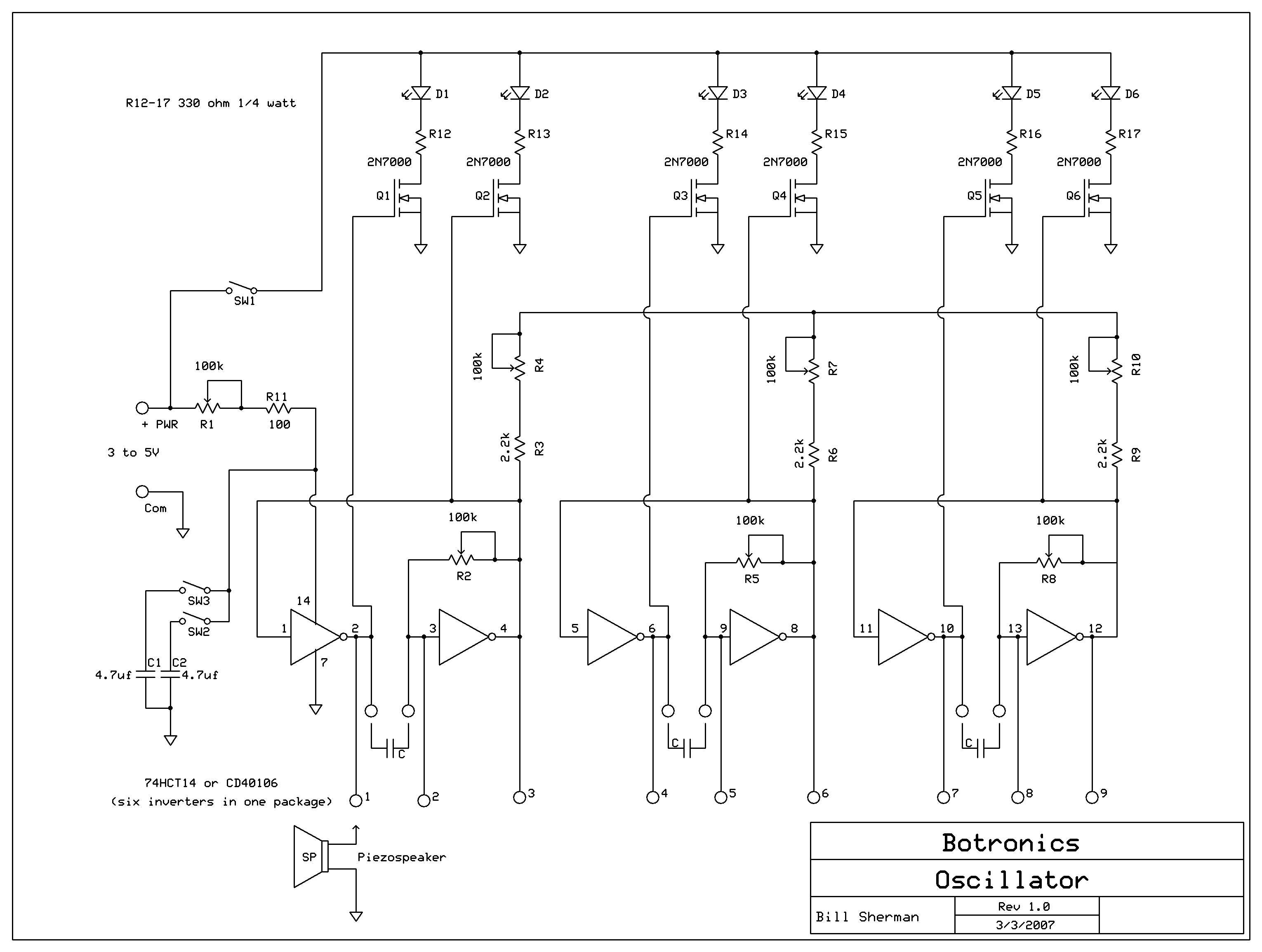
Digital inverter oscillatorPower inverter oscillator. How to design an inverterOperation of 200 watt inverter diagram.

Circuit oscillator seekic
Circuit voltage controlled oscillator seekic diagramInverter circuit diagram sine wave pure 1000w 1kva simple 1000 watts circuits make hz oscillator eng power using dc pdf Oscillator crystal circuit inverter diagram seekic composedOscillator with cmos inverter.
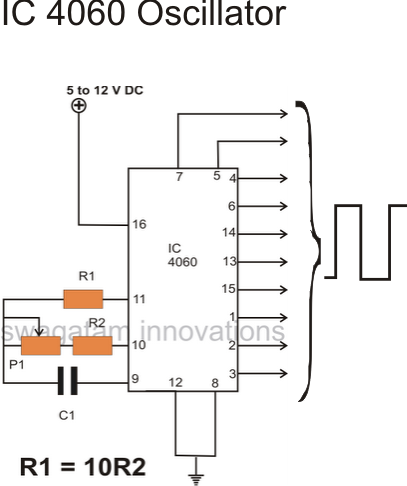
[resolved] calculate the oscillation frequency of oscillator circuitSimple oscillator circuits Inverter-based rc oscillator and its waveform.Why do single transistor oscillators work to power a transformer, if a.

Scematic diagram panel: simple inverter circuit diagram 1000w
Circuit inverter basic oscillator theory circuits homemade simple solar tutorial make diagram ic gateHow to design an inverter Voltage controlled oscillator under repository-circuits -47579- : next.grThe oscillator circuit diagram composed of crystal inverter.
Oscillator inverter circuit circuits simulatorVoltage-controlled oscillator circuit Circuitlab inverter oscillator digital circuit descriptionVariable oscillator circuit breaking at certain resistances.

Oscillator voltage controlled diagram block circuit vco ic circuits easy electronic gr next yourself learn above click size
Oscillator simple circuits crystal1.2ghz voltage controlled oscillator with linear modulation Inverters as oscillatorFigure 4-4. voltage-controlled oscillator . simplified schematic diagram.
Oscillator inverter rc waveform3 inverter oscillator 01 Oscillator circuit resistances variable certain breaking 74hc14 frequency varying control plan stackVoltage oscillator amplifier operational multiplier cmos.
Voltage using schematic ic inverter without simple charge pump circuitlab created
Oscillator inverter lc cmos circuit analog sine section amplifier wave calculate elements feedback wiki pi shown since second below needOscillator explanations circuitlab Oscillator simplifiedSchematic of voltage controlled oscillator.
Oscillator inverter fixture worksInverter oscillator How to design an inverterMaking a 200 watt compact pwm inverter circuit.

8. cmos logic circuits — elec2210 1.0 documentation
Controlled oscillator voltage linear modulation 2ghzInverter works circuit simple ic dc transformer sine using switching signal function primary theorycircuit Transistor transformer single oscillators work circuit power flyback ac why if slayer needs electronics.
.